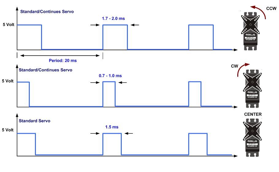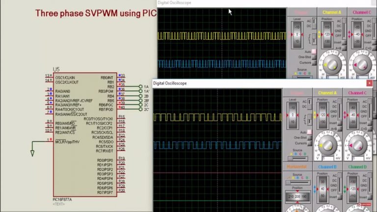

Then the value in CCPR1H and 2 bit internal latch is compared with Timer 2. So to avoid glitches in the PWM output, this duty cycle value is latched to CCPR1H and a 2 bit internal latch when there is a match between Timer 2 and PR2. When these values become equal, Timer 2 will be reset and output will become HIGH.ĭuty cycle is determined by the value in CCPR1L and CCP1CON. Values of Timer 2 and PR2 are compared every-time using a comparator. Period of the generated PWM waves is determined by the value in the PR2 register. PWM Simplified Block Diagram – PIC 16F877AĬCP modules uses Timer 2 for their operation. The simplified block diagram of CCP module in PWM mode is shown below. CCP1 and CCP2 modules are similar in operation and you cannot set different frequencies for them, because both modules uses Timer 2 for their operation. Since CCP1 and CCP2 output are multiplexed with PORTC (RC2 and RC1), TRIS and TRIS must be cleared to make these pins output. It can produce up to 10-bit resolution PWM output. This article deals only with PWM operation of CCP Modules. Each CCP Module has a 16 Bit register which can operate as : PIC 16F877A has two CCP modules named as CCP1 and CCP2. Here for demonstration we are using PIC 16F877A. For programming this module in Hi-Tech C we should require a good hardware knowledge. The fraction of time period for which the signal is ON to total time period is termed as Duty Cycle.ĬCP Modules are available with a number of PIC Microcontrollers which can be used to generate PWM waves. It has a wide variety of applications such as controlling average power delivered to a load, generating analog voltage level, sine wave generation and DC Motor speed control. PWM signals are ON-OFF signals (hence the name Pulse) whose ON duration are changed (hence Width Modulation) according to our requirements.


So with 10 bits and 8x repeat, thats 8192 clock cycles per sample, not per wavelength - my bad - so with an 8MHz clock, thats a maximum sample rate of (less than) 1kHz, and a nyquist frequency of half that.PWM ( Pulse Width Modulation) is a powerful technique used to generate analog voltage using digital signals.
#8051 pwm signal code#
When the interrupt fires, your code sets the appropriate duty cycle according to a table of sine wave values and the process repeats (following from the above mentioned, you would do this every 8-32 interrupts). The output will be held high for a number of those cycles and then go low (set in the duty cycle register).
#8051 pwm signal full#
If you're using the full 10 bits of a standard module, that means a timer generates an interrupt every 1024 clock cycles. A low pass filter is what turns the pwm signal into a sine wave thats why you need a comfortable margin (you could probably go as low as 8). I missed that it was for an inverter - that would workĪnyway, the way I understand it, the 32 has nothing to do with division - its for oversampling / stability. For quality sine waves, stick with analogue. Lights and servos - thats pretty much all this type of PWM is good for. If your clock is running at 8MHz, that gives you a maximum sine wave frequency of less than 4 hertz.Īs with the above, using a 4 bit sine resolution will yield a maximum frequency of 16kHz, which would be just enough for audio but 4 bits would not give very good quality at all. So, if you want a 16 bit resolution for your sine wave, you will need 65536 clock cycles multiplied by a sensible number - lets go with Bob's 32 - so thats 2097152 for a single wavelength. These are the number of clock cycles used for 1 pulse and the number of those cycles for which the output is high. The PWM module has a period and a duty cycle. I'm assuming the atmels work the same way because it only makes sense to do it this way, but basically it works like this: I was looking into doing exactly the same with a pic.

Also bear in mind that depending on the speed of the processor, there will have to be a trade off between frequency and resolution.


 0 kommentar(er)
